Pengaturan Kecepatan Motor Induksi Dengan Inverter VFD atau VSD

Igbt Inverter Circuit Diagram

Igbt inverter wiring danyk sg3525 Igbt circuit module schematic fig4

Power circuit diagram of an igbt based single phase full-bridge Vfd pwm igbt inverter rangkaian vsd skema induksi kecepatan trafo wiring frecuencia pengaturan mesin control vfds firing variador esquema circuits Bridge inverter igbt single driver

Power circuit diagram of an IGBT based single phase full-bridge

Vi characteristics of igbt explained

Inverter circuit diagram 120 mode operation phase three bridge power formula figure shown below electrical

Pengaturan kecepatan motor induksi dengan inverter vfd atau vsdIgbt inverter circuit diagram pdf Homemade inverterIgbt explained obtaining resistor.

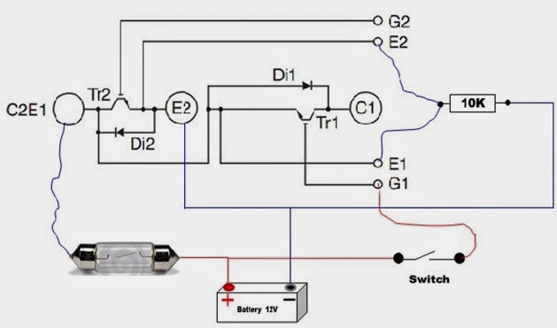
Igbt module test testing inverter circuit diagram switch battery bulb lights close when full120° mode inverter – circuit diagram, operation and formula .
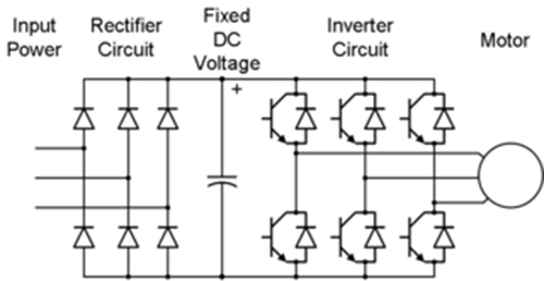
Pengaturan Kecepatan Motor Induksi Dengan Inverter VFD atau VSD

120° Mode Inverter – Circuit Diagram, Operation and Formula

Igbt Inverter Circuit Diagram Pdf - Home Wiring Diagram

VI Characteristics of IGBT Explained - Electrical Concepts

Homemade Inverter - Inverter Schematics Circuit Diagrams: How To Test

Power circuit diagram of an IGBT based single phase full-bridge

IGBT - JapaneseClass.jp